
Temperature conditions
Tf, holding temperature Th and maximum temperature limit Tm are different parameters. Ambient temperature and heat generated by the equipment must also be considered.
A non-resettable protective component that interrupts the circuit
when excessive temperature occurs.
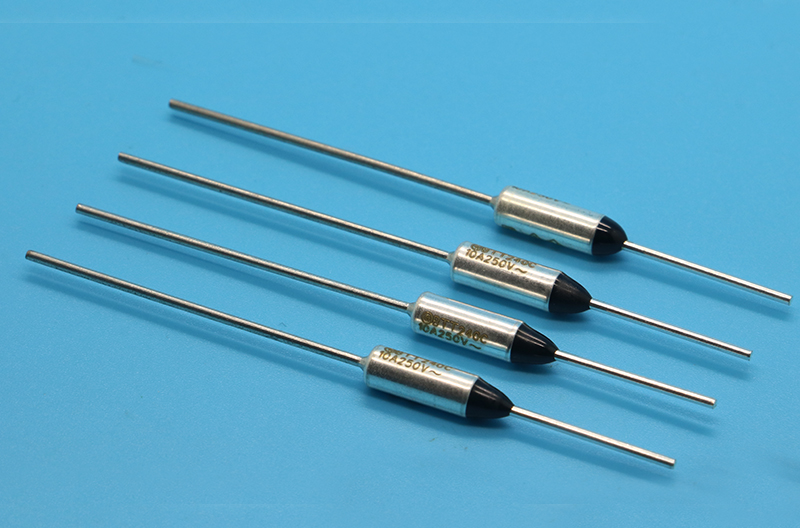
The BTT series combines a metal case with an organic thermal sensing material. It opens the circuit under specified temperature conditions and cannot reset after operation.
Its role differs from a thermostat used for repeated temperature control. Suitability must be checked against the equipment's temperature, load and installation conditions.
21 discrete ratings. All listed approvals for the 147°C option are pending in the source.
Source: manufacturer OT-BTT-EPS-F/5 and BTT datasheet, dated 22 May 2026 (files marked effective 1 July 2026). Verify approvals, Th and Tm for the selected model and rated current.
Consider the application, electrical load and actual installation together.
Tf, holding temperature Th and maximum temperature limit Tm are different parameters. Ambient temperature and heat generated by the equipment must also be considered.
Please provide operating voltage, normal and abnormal current, and load type.
Check the heat transfer path, mounting position and connection method against the manufacturer's specified conditions.
These application examples are starting points for discussion, not confirmations of suitability or supply experience for a particular device.
See the introduction process| Tf (°C) | Operating temp. (°C) | Th / 10 A (°C) | Th / 15 A (°C) | Tm (°C) |
|---|---|---|---|---|
| 73 | 69±2 | 58 | 50 | 300 |
| 77 | 74±2 | 62 | 54 | 300 |
| 84 | 80±3 | 69 | 61 | 300 |
| 94 | 91 +3/−2 | 79 | 71 | 300 |
| 99 | 95±2 | 84 | 76 | 300 |
| 113 | 108 +2/−3 | 98 | 90 | 400 |
| 121 | 117±3 | 106 | 98 | 400 |
| 128 | 124±3 | 113 | 105 | 400 |
| 133 | 129 +3/−2 | 118 | 110 | 400 |
| 142 | 140±2 | 127 | 119 | 400 |
| 147 * | 142±2 | 117 | 107 | 400 |
| 152 | 149±2 | 137 | 129 | 400 |
| 157 | 152±2 | 142 | 134 | 400 |
| 167 | 164 +2/−3 | 152 | 144 | 400 |
| 172 | 168±3 | 157 | 149 | 400 |
| 184 | 180±2 | 169 | 161 | 400 |
| 192 | 189±2 | 177 | 169 | 400 |
| 216 | 213±3 | 200 | 193 | 480 |
| 229 | 225±2 | 210 | 205 | 480 |
| 240 | 238±2 | 210 | 205 | 480 |
| 257 | 254±3 | 210 | 205 | 480 |
Th is holding temperature; Tm is maximum temperature limit. The datasheet identifies Th/Tm as PSE parameters, but marks every approval for 147°C (*) as pending. The values in that row do not indicate approval.
Example BTT010142B: 010 means 10 A (015 means 15 A); 142 means Tf 142°C; B means the normal series with an 18 mm lead. A/B designate 18 mm and C/D designate 43 mm. A/C are special series; B/D are normal series. Check L1 and L2 against the drawing.
Confirm lead length, connection method and operating conditions before ordering. A thermal fuse must not be used as a current fuse.
For product and specification inquiries, contact 清水 葉葉.